01 FRONT VIEW · A / B
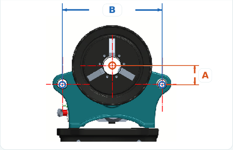


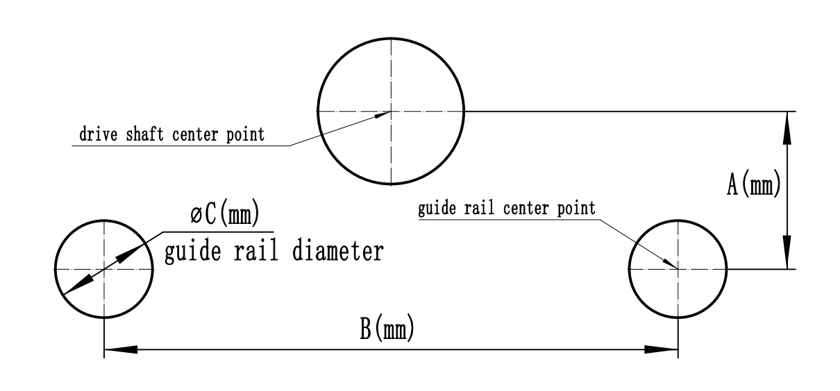
Different drive machines require different mounting plate dimensions. Measure A, B and C as shown below and record all values in millimeters before ordering. Spindle center to guide rod center, measured vertically. Between the centers of the two guide rods, measured horizontally. Measure the outside diameter of the guide rod. Record all three dimensions in millimeters and provide them with your inquiry or order. Please measure and provide dimensions A, B and C before ordering to ensure the mounting plate fits your machine correctly.Pipe Roll Grooving Machine Video
Features of Manual Hydraulic Roll Groover Machine
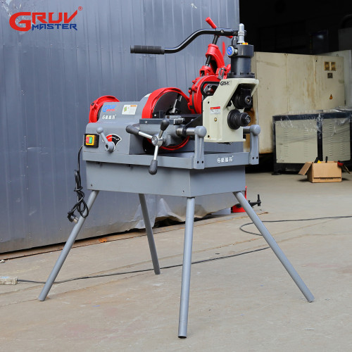
● Model RG-H1X Manual Hydraulic Roll Grooving Assembly is designed to groove steel pipes by mounted power drive or horizontal threading machines● It is a lightweight tool for grooving 2" to 8" (DN50~DN200) steel pipe● Compact design and rugged structure enable unit for mass fabrication duty on jobs● The unique combination of the hydraulic feeding pump and the groove depth lock knob guarantees premium grooves and optimal efficiency.Pipe Roll Grooving Machine Parameter  Model:RG-H1XSuitable materials:Carbon Steel,SS PipeFabrication Capacity:2"-4" SCH10/405"-8" SCH10/20Max wall thickness:6mmPacking gross weight:29kgsPacking size:38*42*47cmStandard Parts of RG-H1X Roll Groover Item Number DescriptionNet weight911074Drive roller 2"~6" (Φ60~Φ168)1.30kg911075Drive roller 8" (Φ219)1.30kg912018Groove roller 2"~6" (Φ60~Φ168)0.45kg912032Groove roller 8" (Φ219)0.45kg911018Drive bar adapter2.30kg913006Support Bench2.20kgResources of RG-H1X Roll Grooving Machine Roll Grooving Machine Configuration
 Hydraulic pump
High-quality seal parts ensure long-term field usage without leaking
Fine-machined cylinder with accurate sizesThe proper-hardened piston rod of long-lifeBuilt-in groove depth adjusting rod
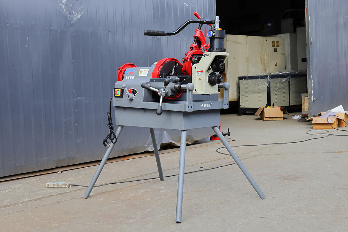 Adapter plate
 to fit on threading machineWork with 2",3",4" pipe threading machine
 Groove Roller
one set 2"~6" (Φ60~Φ168)one set 8" (Φ219)
 Drive roller
one set 2"~6" (Φ60~Φ168)one set 8" (Φ219)Mounting Plate & Drive Alignment Diagram
 H1X and H2X pipe grooving attachment feature a detachable mounting plate.
The mounting plate is precision laser-cut to accommodate different machine sizes or model combinations.
It is compatible with various threading machines or power drives, including 300-type drive units and other well-known brands.
Mounting Plate Measurement Guide
01 FRONT VIEW · A / B
02 SIDE VIEW · C
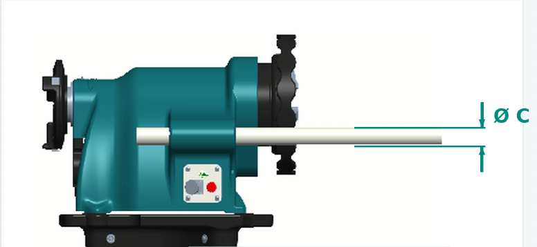 Guide rod cross-sectionMeasure the outside diameter of the guide rod.
Ø C
Vertical center distance
Horizontal center distance
Guide rod diameter
IMPORTANT: For A and B, measure center-to-center, not from edges or machine housing.
MEASUREMENTS REQUIRED BEFORE ORDERING
AVertical center distanceRecord in mm
BHorizontal center distanceRecord in mm
CGuide rod diameterRecord in mm
Pipe Roll Grooving Machine Comparasion